Ryerson Computer Science CPS511: Computer Graphics
(go back)Course Map
Rough Notes
Intro
3D Modelling
3D graphics are different from 2D pixel-based graphics in that 3D is based on models created and manipulated by using mathematics (geometry)
Rendering, important sub-tasks
- Scan conversion (rasterization)
- Visible surface algorithms
- lighting and shading
Image Formation
Global lighting techniques
Ray tracing
good for shiny, etc; simulates light travelling FROM the eye to the light source
Radiosity
math intensive, slow, but good for cloth
Local lighting
Rasterization
- Very fast, small memory footprint; but shadows, reflections, etc are more difficult
- figures out which pixels to turn on
- interpolates the colour of interior pixels
Double buffering
Uses two buffers: a front and a back
- front: currently being displayed
- back: currently being filled
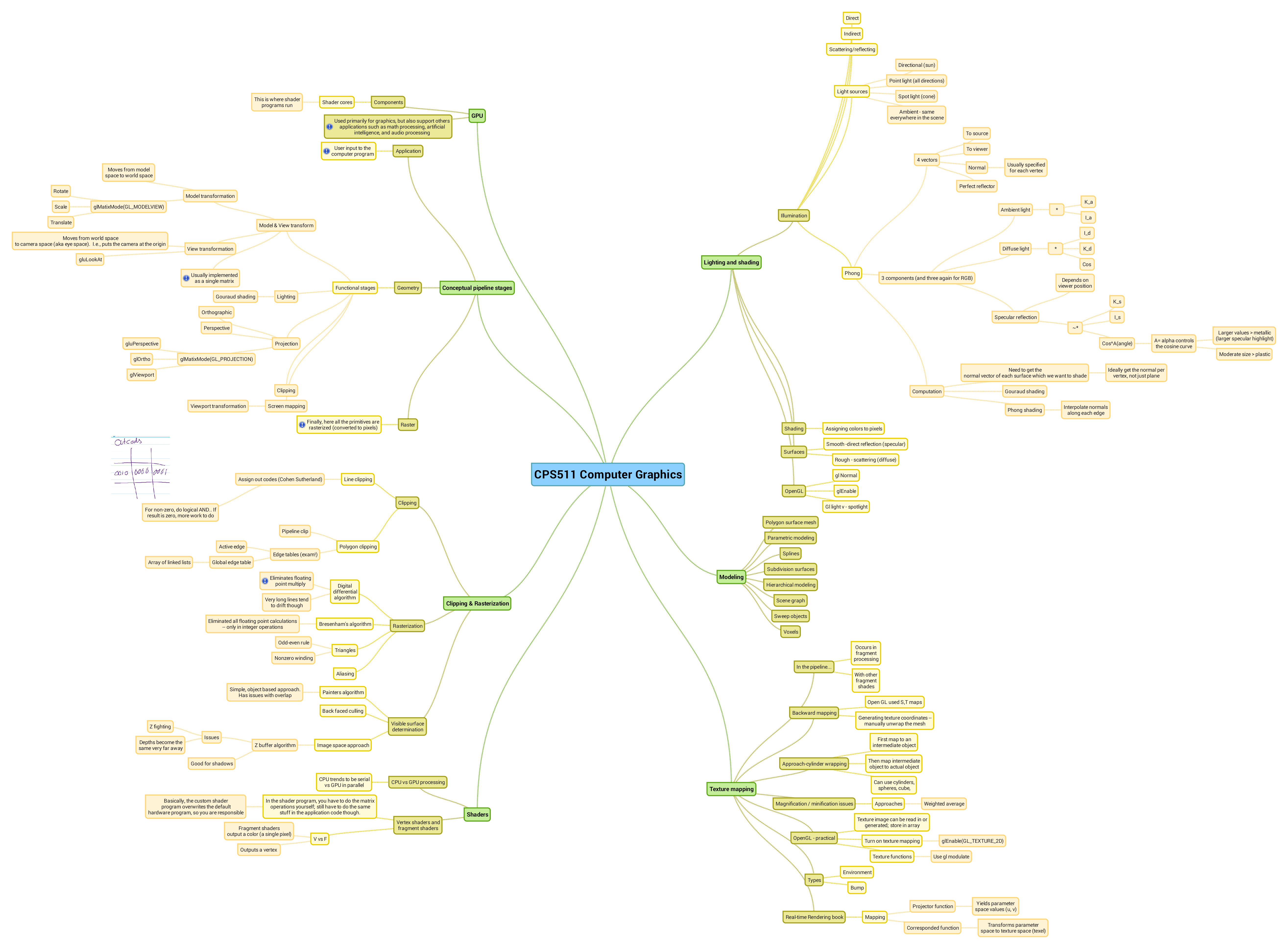
Conceptual pipeline stages
From Real-Time Rendering 2nd Ed.
Pipeline diagram from lecture notes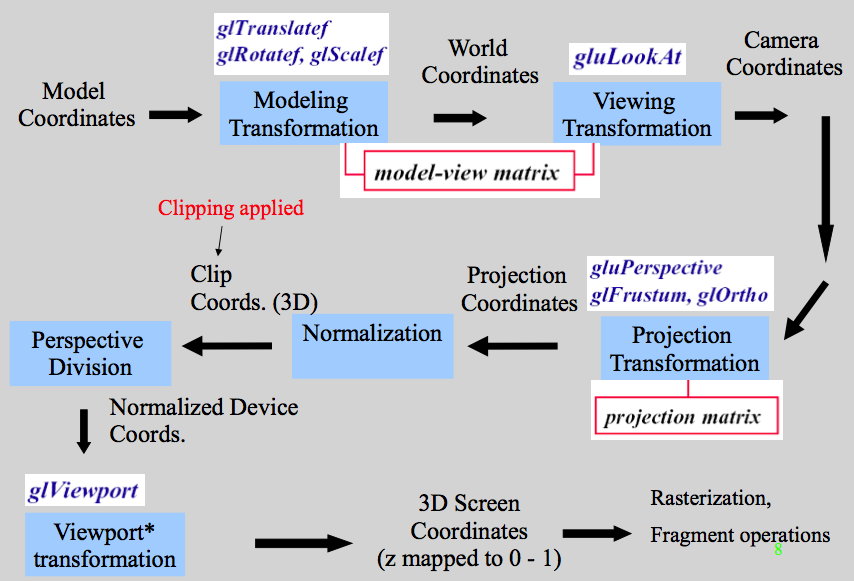
- Application Stage
Computer program provides an input model of vertices
- Geometry Stage
- Model & View transform
- Model transformation
- Moves from model space to world space
- glMatixMode(GL_MODELVIEW)
- Rotate glRotate()
- Scale glScale()
- Translate glTranslate()
- View transformation
- Moves from world space to camera space (aka eye space). I.e., puts the camera at the origin
- gluLookAt(CamPosition, CentreOfView, UpVector)
- Usually implemented as a single matrix
- Model transformation
- Lighting (done in eye-coordinates)
- Gouraud shading
- Projection Transformation
- Orthographic
- Perspective
- glMatixMode(GL_PROJECTION)
- gluPerspective
- glOrtho
- glViewport
- Clipping Algorithms
- Viewport Transformation
- glViewport();
- Model & View transform
- Rasterization Stage
Here all the primitives are rasterized (converted to pixels)
- Fragment Operations Stage
Additional per-pixel operations are performed here
Geometric Transformations
Note: geometric transformations are applied via matrix multiplication, and matrix multiplication is not commutative, so order is important. Order is like this:
$M_{final} = TransN\ x\ ...\ x\ Trans3\ x\ Trans2\ x\ Trans1$
Modelling Transformation
Transforms the model into the world space
- glScale
$\begin{pmatrix} x & 0 & 0 & 0 \\ 0 & y & 0 & 0 \\ 0 & 0 & z & 0 \\ 0 & 0 & 0 & 1 \end{pmatrix}$
- glRotate (CCW)
- About Z
$\begin{pmatrix} cos(\theta) & -sin(\theta) & 0 & 0 \\ sin(\theta) & cos(\theta) & 0 & 0 \\ 0 & 0 & 1 & 0 \\ 0 & 0 & 0 & 1 \end{pmatrix}$
- About X
$\begin{pmatrix} 1 & 0 & 0 & 0 \\ 0 & cos(\theta) & -sin(\theta) & 0 \\ 0 & sin(\theta) & cos(\theta) & 0 \\ 0 & 0 & 0 & 1 \end{pmatrix}$
- About Y
$\begin{pmatrix} cos(\theta) & 0 & sin(\theta) & 0 \\ 0 & 1 & 0 & 0 \\ -sin(\theta) & 0 & cos(\theta) & 0 \\ 0 & 0 & 0 & 1 \end{pmatrix}$
- About Z
- glTranslate
$\begin{pmatrix} 1 & 0 & 0 & x \\ 0 & 1 & 0 & y \\ 0 & 0 & 1 & z \\ 0 & 0 & 0 & 1 \end{pmatrix}$
Viewing Transformation
Redefines world objects to camera objects; converts cam coords to world coords (camera eye aka viewing coordinates)
Note: OpenGL's gluLookAt() requires that the up-vector parameter must not be parallel to the direction that the camera is pointed in. If that happens the view matrix breaks.
Building a viewing transformation matrix:
- Build the translation matrix to move everything to the origin
- Build the rotation matrix to orient everything as desired
$Pcamera = R \cdot T$ (this is the viewing transformation)
Projection Transformation
Changes the view volume (like adjusting the camera lens)
- gluPerspective, glFrustum, glOrtho
- Projection Plane is the near plane
- Orthographic (parallel) projection is unrealistic, non-human eye-like view, while perspective projection has more distant points appearing to be smaller (like the human eye)
- This stage also includes:
- Clip coordinates -> perspective division
- Normalized device coordinates -> viewport transformation [glViewport]
Lighting and shading
Lighting is is calculating the luminous intensity at a particular point, while shading is assigning colors to pixels
Illumination
Direct illumination is light that came directly from a light source, while indirect is light that has bounced off another object before reaching the given object
Light sources
- Directional (sun)
- Point light (all directions)
- Spot light (cone)
- Ambient - same everywhere in the scene
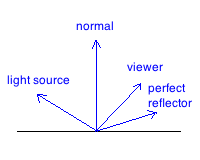
Phong Lighting
Consists of 4 vectors: light source, viewer, normal, and perfect reflector
There are 3 components for each of RGB:
- Ambient light = $K_a * I_a$
- Diffuse light = $K_d * I_d * (l \cdot n) $
- Specular reflection = $K_s * I_s * (v \cdot r)^{\alpha}$
- Depends on viewer position
- $\alpha$ controls the cosine curve: larger == larger specular highlight (metallic) vs smaller $\alpha$ == moderate sized highlight (plastic)
Lighting Computation
- Need to get the normal vector of each surface which we want to shade
- Ideally get the normal per vertex, not just plane
Shading
Assigning colors to pixels
Flat Shading
- simplest approach, but poor quality result
- calculates illumination for a single point in each polygon
- looks blocky
- Solution to this problem is to get the normal for each vertex. This is used in Gouraud and Phong
Gouraud Shading
- Performs Phong Lighting at every vertex (this is what OpenGL does)
Phong Shading
- Interpolate normals along each edge
- Applies the Phong Lighting model at every pixel, instead of just every vertex
Surfaces
- Smooth -direct reflection (specular)
- Rough - scattering (diffuse)
Misc
- exam: scattering / reflecting light
- Ray-Tracing: works best for shiny objects
- an object appears red under white light because all of the non-red light rays were absorbed
Light Components
- Ambient: an even level from no particular direction (global lighting)
- Diffuse: comes from a particular direction, and reflects off surfaces with an intensity proportional to the angle at which it strikes
- Specular: comes from a particular direction, and creates a bright spot depending on the viewer's position relative to the light as well as based on the surface material
Exam: what does "alpha" control in specular highlight EQ? size of the specular highlight (larger->metal-like)
If multiple light sources, simply add all the terms
Modelling
Considerations in Selecting a Scheme
- Easy to create and manipulate
- Memory usage
- Surface vs Volume representation
- If you don't need volume information, then surface will suffice; sometimes you need volume info though
- Parametric vs Implicit
- implicit (like the implicit equation for a sphere) is good for collision detection
Final Exam
- understand the major categories, differences, general basics of each
- voxels - is it surface vs volume?
- list & describe 5 techniques
Polygon Surface Mesh
Polygons are very unstructured though, so harder to work with (than say, an ellipse)
Polygon tables: like .obj file, list of polygons, edges, vertices, etc
Parametric Modelling
- useful for modelling surfaces where continuity is important
Splines
- interpolated, approximated
Subdivision Surfaces
- interpolated, approximated
- types: loop, modified..., catmull-clark
Hierarchical Modelling
Scene Graph
Graph of transformations applied to the leaf nodes (the objects)
Sweep Objects (Assignment 2)
Constructive Solid Geometry
Use boolean expressions and objects as operands, another object is the result of the operation
Voxels
Area is partitioned into uniform grid; each space is occupied by a voxel
Blobs & Metaballs
Useful for soft contours, often muscles
Fractals
Good for making realistic looking natural objects (mountains, plants, clouds, etc)
Texture mapping
Location
From Angel notes: images and geometry flow through separate pipelines that join during fragment processing
Backward mapping
- Open GL used S,T maps
- Generating texture coordinates --manually unwrap the mesh
Approach-cylinder wrapping
- First map to an intermediate object
- Then map intermediate object to actual object
- Can use cylinders,spheres, cube,
Magnification / minification issues
Approaches
- Weighted average
OpenGL - practical
- Texture image can be read in or generated; store in array
- Turn on texture mapping
- glEnable(GL_TEXTURE_2D)
Texture functions
- Use glModulate()
Other Types
Environment
Aka reflection mapping; uses a picture of an area (environment) to be reflected from a surface. Good for simulating highly reflective / mirror-like surfaces
Bump
Provides the appearance of a bumpy surface. Since its only a simulated set of bumps and the vertices aren't actually moved, the edges of the object will appear flat
Real-time Rendering book
Mapping
- Projector function
- Yields parameterspace values (u, v)
- Corresponded function
- Transforms parameter-space to texture space (texel)
Clipping & Rasterization
Clipping
Line clipping
- Assign out codes (Cohen Sutherland)
- For non-zero, do logical AND.. If result is zero, more work to do
Cohen Sutherland Line Clipping (with Outcodes)
Create a 3x3 grid of "outcodes", where the centre is the viewport which has a code of 0000
- For each line segment (pair of points):
- If both points codes are 0000, it is inside the viewport, so keep it and move on to the next line
- Else:
- Perform boolean AND the the points outcodes; if != 0
- Its totally outside the viewport so throw away
- Else:
- Choose one of the points and establish a dividing line based on the first '1' bit in that point (match up with the corresponding 1 bit in other outcodes), and discard part of the line that is on the wrong side of the dividing line
- Perform boolean AND the the points outcodes; if != 0
Polygon Scan Conversion
Process "scan lines" one at a time from left to right to determine:
- Polygon Edges that are intersected
- When we are interior and when we are exterior
Polygon Clipping - Sutherland-Hodgeman Algorithm
Essentially, for each edge in the clip window, you output vertices that are on the "in" side of that edge. After calculating output vertices for an edge, redraw the polygon with only those vertices. So when you finish the last edge, the output vertices will be the final clipped polygon.
Polygon Scan Conversion - Active Edge Table
Algorithm for finding the edges
- For each scan line, add entries to the Global Edge Table (GET)
- entry $(y_{max}, x_{@ymin}, 1/slope)$
- table is indexed by $y_{min}$
- For each scan line, add entries to Active Edge Table (AET)
- entry $(y_{max}, x_{@scanline-edge-intersection}, 1/slope)$
Rasterization
Digital differential algorithm
- Eliminates floating point multiply
- Very long lines tend to drift though
Bresenham's algorithm
- Eliminated all floating point calculations-- only in integer operations
Triangles
- Odd-even rule
- Nonzero winding
Aliasing
Visible surface determination
Painters algorithm
- Simple, object based approach.Has issues with overlap
Back faced culling
Image space approach
- Z buffer algorithm
- Issues
- Z fighting
- Depths become the same very far away
- Good for shadows
- Issues
GPU & Shaders
GPU Components
Shader cores
- This is where shader programs run
Used primarily for graphics, but also support other applications such as math processing, artificial intelligence, and audio processing
CPU vs GPU processing
CPU trends to be serial vs GPU in parallel
Shaders
Shaders are high-level language (GLSL, etc) programs that are injected into the (formerly) fixed graphics pipeline at various stages. Popular ones are vertex shaders and fragment shaders.
Shaders override functionality that was previously fixed in the pipeline
- Basically, the custom shader program overwrites the default hardware program, so you are responsible for multiplying matrices and so on
Vertex Shader
- Input is a raw model-space vertex
- Output is a vertex that has been transformed (hopefully) to camera space, and is colored
Fragment Shader
- Input a pixel intensity (RGB)
- Output a possibly modified pixel; shading, texturing, fog, etc